After solving the model, spreadsheet results for the analysis and design become available. These can be accessed through the Results menu or the Results toolbar. The information presented below is only relevant for Concrete Floor Slabs. For detail report information see the Elevated Slab - Design Strip Detail Reports topic.
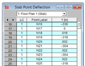
The Slab Point Deflection spreadsheet displays the absolute deflection of points in the slab for each load combination. Deflection is reported in the vertical global Y-axis. You can select the results per floor plan by selecting from the drop-down box at the top.
Note:
The maximum vertical deflection (in the global Y-axis) is reported for each Span of each Support Line. Under the Standard tab the deflection is reported separately for the Dead Load, the Live Load, and the combined Dead and Live Load. For each Load Category an absolute maximum deflection is reported over the span, and then a ratio of clear span to deflection is also reported. The clear span (face of support to face of support) is shown in the Length column.
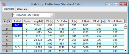
Values which exceed the allowable deflections defined in the Slab Design Rules are shown in red. Alternate deflection criteria defined in the Slab Design Rules is shown on the Alternate tab.
Note:
The Slab Results/Rebar spreadsheet reports the design results for the Design Strips.
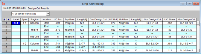
Below are descriptions of each column in the Design Strip Results tab:
| Spreadsheet Column | Description |
|---|---|
| Label | Support Line Label |
| Span |
The Support Line Span defined by Support Point to Support Point. Note: When the Span is the same number (i.e. 1-1) this indicates a cantilever support line span. |
| Region | Label for the Design Strip within the Span |
| Location | The end of the Design Strip (Start or End) which the design results are presented for, based on the order in which the Support Line was drawn (Start is first click, End is second click) |
| UC Top | Controlling Unity Check for bending when the top face of the slab is in tension. This is the ratio of moment demand to moment capacity, based on the specified rebar. |
| Top Bars | Required rebar at the top face of the slab, as determined by analysis. This quantity of rebar is sufficient to meet all code requirements unless UC Top is greater than 1.0. If welded wire bars are designed, the output result will be preceded by a “D” instead of “#” to indicate wire bar size. |
| Length | Distance the top rebar must project from the centerline of support into this Span (including development length). The total piece length of the top bar would be equal to the sum of the Lengths from the two adjacent Spans. |
| Gov Design Cut | The Design Cut within the Design Strip which produced the controlling UC Top value. |
| UC Bot | Controlling Unity Check for bending when the bottom face of the slab is in tension. This is the ratio of moment demand to moment capacity, based on the specified rebar. |
| Bot Bars | Required rebar at the bottom face of the slab, as determined by analysis. This quantity of rebar is sufficient to meet all code requirements unless UC Bot is greater than 1.0. If welded wire bars are designed, the output result will be preceded by a “D” instead of “#” to indicate wire bar size. |
| Length | Length of the bottom bars in this Span. Since bottom bars are always designed as continuous over the entire span, this number is always the length of this Span (centerline to centerline). |
| Gov Design Cut | The Design Cut within the Design Strip which produced the controlling UC Bot value. |
| UC Shear | Controlling Unity Check for one-way out-of-plane shear in the slab. This is the ratio of shear demand to concrete shear capacity, ignoring any steel shear capacity. |
| Gov Design Cut | The Design Cut within the Design Strip which produced the controlling UC Shear value. |
Note:
The Slab Results/Rebar spreadsheet reports the design results for the Manual Design Cuts.
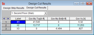
This spreadsheet only reports Manual Design Cuts, as opposed to Automatic Design Cuts.
Below are descriptions of each column in the Design Cut Results tab:
| Spreadsheet Column | Description |
|---|---|
| Label | Manual Design Cut Label |
| Gov Mu Top |
Total bending moment across the Cut which results in the top face of the slab being in tension. This is the maximum bending moment which occurred considering all solved Load Combinations. |
| Gov Mu Bot | Total bending moment across the Cut which results in the bottom face of the slab being in tension. This is the maximum bending moment which occurred considering all solved Load Combinations. |
| Gov Vu | Total vertical shear through the plane of the Cut. This is the maximum shear which occurred considering all solved Load Combinations. |
Note:
The Slab Forces spreadsheet is accessible through the Results Toolbar and the Results Menu. This spreadsheet lists all of the slab forces for a given floor. The spreadsheet is organized by Support Line. The forces for each support line are broken out by Span, and the forces for each Span are broken out by Region.
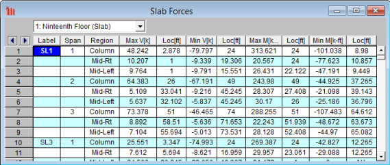
Below are descriptions of each column in the Slab Forces spreadsheet:
| Spreadsheet Column | Description |
|---|---|
| Label | Support Line Label |
| Span |
Span Number of Support Line |
| Region | Region within Span. |
| Max V & Loc | Maximum shear in that region with in that span. The Loc Column states where in that span the maximum is located. |
| Min V & Loc | Minimum shear in that region with in that span. The Loc Column states where in that span the maximum is located. |
| Max M & Loc | Maximum moment in that region with in that span. The Loc Column states where in that span the maximum is located. |
| Min M & Loc | Minimum moment in that region with in that span. The Loc Column states where in that span the maximum is located. |